The last major item that completes the assembly of the dash is a pretty complicated system in itself; the heater box. This assembly contains a blower motor, a speed control, several air redirection flappers, defrost ports, a water heater radiator core, and a small pile of rubber seals. To top it all off, it fills the remaining holes in the firewall as well as seats up against the passenger side cowl vent.
Of course yours truly, being an eternal optimist, thought he could just clean it up, throw some paint on the outside, and put it back in. That is, until I really got to looking at it. The motor was all crusty, the paper defroster plenum was crushed, and there was a mummified family of mice residing within. I searched for parts and soon discovered that all of the parts required to rebuild a heater box were available. The most important, being a
seal kit since all of mine were deteriorated long ago.
I placed an order with NPD and began to disassemble the box starting with the removal of the old heater hoses and the removal of the defroster plenum by removing the four screws holding it on. Next, the clips could be popped off and the box split in half. Normally, I'd spend the time giving a full set of instructions for rebuilding a heater box but there are already plenty of sources for that:
A VMF Thread,
A Mustang Monthly online article, a
CJ Pony Parts writeup (by VMF member 66FSTBCK), and more if you do some Goggling. That's not to say I didn't take lots of pictures of the various steps though.
Upon removal of the heater core, I decided to flush it out with a hose tucked up against one of the water tubes. I ran a lot of water through it until the water became less and less red-tinted. After that, I checked the core for leaks which is really as easy as sticking your thumb over one of the water tubes and sucking on the other one. Yes, I said "sucking". According to more knowledgeable folks than I, you can draw a vacuum of right around 14 bar just with your own mouth. So use whatever imaginary image that works for you and wrap your lips around that pipe, create a vacuum, and just sit there and wait to see if you can detect any reduction in vacuum over like 10 seconds. If not, you're good to go, which mine was. Seriously, there's a web page that
describes the process. Just remember, I flushed the heck of that core first.
Another sub-task that this rebuild required was the breaking down of the blower motor which is removed from the fan housing by removing four nuts. The fan can then be removed by removing the lock screw from the shaft and sliding the fan off the shaft. Unfortunately, mine didn't just pop off, I held the fan and tapped lightly on the shaft being very careful not to deform the end. After the fan came off, I found that the shaft then seemed like it was jammed and I was worried that I'd ruined the motor. I removed the motor from its mounting plate and pulled the motor apart. The shaft came free so I blasted the motor shell and repainted it since it was already apart.
The difficult part of the task was cleaning up the mess. I removed as many metal parts as I could from the box and blasted them. Then I masked off all of the surfaces of the box except for the remaining metal parts that are riveted on, and blasted them as well. I used lacquer thinner to clean the fiberglass portions of the box inside and out. All metal parts were then sprayed with etching primer and semi-gloss engine enamel. The box was then deemed ready for assembly so I awaited the arrival of the new parts.
 |
| Starting Out |
 |
| Hoses off. |
 |
| Front View |
 |
| Top View |
|
 |
| Cracked open |
 |
| Heater core removed. |
 |
| Flushing the core |
 |
| Nasty |
 |
| Mouse mummies. |
 |
| Remove four nuts to pull the motor |
 |
| Hex wrench to remove the set screw for the fan. |
 |
| Gaskets after motor is removed. |
 |
| Face of motor with number stamps. |
 |
| Media blasted motor case. |
 |
| All of the rusty parts. |
After the heater box was completely broken down, I ran all of the metal parts through my blast cabinet. The parts were then primed with etching primer and then painted with semi-gloss engine enamel. The fiberglass box halves were strategically masked off to blast, prime, and paint the cable brackets. Then a dab of silver paint was touched on the various rivets to detail them off.
 |
| All of the media blasted parts |
 |
| All of the freshly primered parts |
 |
| All of the freshly painted parts. |
 |
| Putting the speed control back in. Note the use of strip caulk. |
 |
| Brackets painted and detailed. |
The seal kit contains a complete set of foam and foam rubber seal parts. They're not exactly like the remnants of the original seals but rather better than the originals in that they'll sometimes cover an entire seal surface rather than just strips around the edge of a seal. The kit came with instructions on where the seals go but my own reference pictures helped with determining more exactly where the old seals were on the original metal parts. The seals were affixed to the parts using 3M contact spray adhesive. As with paint, I had to mask off any areas where I didn't want contact cement to be sprayed. A majority of the seals are used on the "flapper box" (as I call it, really, the flapper assembly that switches air into and away from the heater core).
The box was then reassembled by first inserting the flapper box into the fiberglass section containing the fan. The flapper box is affixed to the fiberglass box with two sheet metal screws. The sheet metal heater core support was next laid into position and the inner heater core seal was glued on over the top. The heater core was set into the seal and the other core seal was glued into the side of the box with the speed control. The two halves could then be carefully pressed together making sure not to damage the seals on the sides of the flapper box. The many clips can then be used to clamp the box back together.
 |
| Seal installed on the clean-out door. |
 |
| Seals installed on the "flapper box". |
 |
| Flapper box installed in the vent-side heater box with heater core seal. |
 |
| Heater core installed. |
 |
| Box being reassembled. |
 |
| Channel locks to clamp the sides together while clip is installed. |
The motor seals are affixed to the mounting plate and the motor is bolted onto it, the fan mounted on the motor shaft, and the assembly bolted back into the fan housing of the main heater box. Finally, I clamped new heater hoses onto the heater core supply tubes completing the heater box R&R. I next brought out the heat control panel that's mounted into the left side of the car's dash and adjusted the positions of the cables and marked them on the box with masking tape. This would allow me to easily position them after the box is in the car without a bunch of fiddling around in the cramped space.
 |
| Blower motor mounting plate. |
 |
| Blower motor. |
 |
| Fan affixed to the blower motor. |
 |
| Blower motor affixed to the fan housing. |
 |
| New heater hoses with original style clamps. |
 |
| Ready to go in! Cable positions pre-marked. The cables had matching markings. |
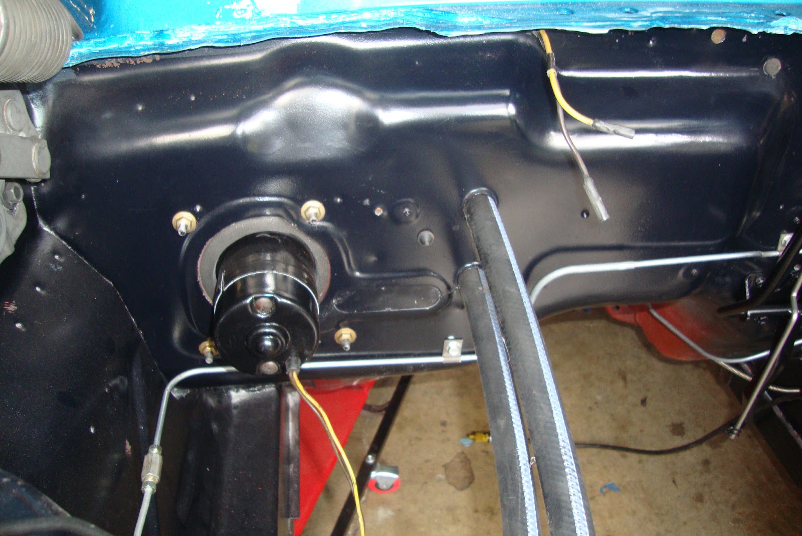
Finally, the box was worked back up under the dash, the hoses snaked through their holes in the firewall, and the mounting studs through the motor port. New speeds nuts were used to mount the box to the firewall. Inside the car, the speed control wires were hooked up and the upper cowl support bolt installed. The control panel was inserted on the left side of the dash and the control cables snaked up over the pedal bracket next to the firewall and directed to their appropriate bracket on the heater box. Finally, the windshield defroster tubes were piped into the top of the defroster plenum.
 |
| Heater installed in the firewall. |
 |
| Speed control wires and upper cowl mount (upper right side of picture). Cables attached to brackets. |
 |
| Cable attached to defroster plenum. |
 |
| Heater Controls Installed |
 |
| defroster hoses hooked up. |


Detailed and thorough as always Alex! Nice job!
ReplyDeleteThis brings up a question that I've never been 100% satisfied with the answer. Does anyone know if it matters which direction the water circulates in the heater core? You would think it doesn't matter...but...maybe it does? Since I swapped the 302 in my car for a crate 351 - the heater hose connections worked out better if I swapped the order of connection at the fire wall. I figure the day I finally fire it up, I'll be able to definitely answer the question :)
rj
I ran across the answer to your question in my heater core studies. The answer is no, the heater core flows either way. However, the factory recommends the top line go to the pump. If you hook it up the other way, it's reported that you wil hear gurgling from the core when you start up while the air bubbles work their way out.
Delete