Now that the fuse box was all tidied up and the under-dash harness was clean, I could go ahead and install it. But first, remember those
firewall pad clips I was waiting for
back in April? I needed those to install the firewall pad first because the fuse box mounts on top of it. Well the pins finally arrived so I was able to install the pad. The 68 "pins" aren't really pins at all, they're more like big rubber plugs that you stuff into holes in the firewall. My car had only 3 of these holes that had previously been plugged up at the factory with sealer so I had to drill a couple of new holes to match up with the pre-punched holes in my original firewall pad as well as the few good reference pictures I could find of people whom had previously installed these pins but usually on after-market pads. The actual installation is pretty straight forward. You just line the pad up with the firewall holes and push the pins through. Well, okay... shoving rubber pins through a firewall hole from about 3/4" back with no ability to guide the end of the pin through the hole (because the pad is between you and the firewall) presented some issues. I overcame this by pushing a screwdriver extension into the hole of the plug and then using that to provide some control over the end of the pin as I worked it through the hole. It worked okay and the pad was in.
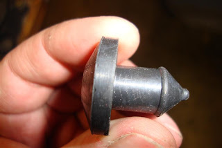 |
| The 68 firewall insulation pad "clip" |
 |
| This is how I installed the clips. |
 |
| The driver side pad. Clips in place. |
 |
| Passenger side pad (left) |
 |
| Passenger side pad (right) |
Now the car was ready to be re-introduced to it's under-dash harness. This "installation" basically required just screwing the fuse box on to the firewall and running the left side of the harness over and in front of the instrument cluster brace and the right side of the harness clipped into 2 (or 3?) obvious places at the underside of the dash top. The firewall seals for the various engine-side pig tails (heater motor/reverse-neutral switch) could then be pushed through their respective firewall holes.
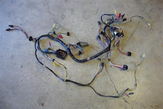 |
| Harness ready to go in. |
 |
| Layed out. |
 |
| Fuse box screwed to the firewall. |
 |
| With the left side of the harness brought over the instrument cluster brace. |
Now for the engine compartment harness. This is a brand new harness that I bought because the old harness is brittle, cracked, and generally untrustworthy. I had also bought a
Mustang Wiring Harness Retainer kit which I had intended to use for the engine harness but the retainers were much smaller and wimpier than the originals, I decided to refurbish and reuse the originals instead.
I used the positions of the various retainers on the original harness as a guide for placing them on the new harness. I also used many reference photos I had taken as well as some web searches to figure out where on the car the retainers fastened. I guided the under-dash connectors through the firewall hole and worked the firewall plug into place and began routing the harness around the engine compartment. When I got to the driver side core support, where the regulator is mounted, I removed a little paint on the two corners where the regulator screws penetrate the core support to provide a suitable ground and then bolted the regulator onto the core support, plugged in the wiring harness and continued routing around the front of the core support to the passenger side. The harness retainers for the front frame from the kit I bought worked fine here. I bolted the horns on (clearing ground points first) and ran their wires to them from the harness. Then I routed the harness through the hole in the passenger side of the core support and up to the starter solenoid on the battery apron. I had also purchased a new convertible top
junction block since my original was pretty much just rotted away and consisted of two terminals bolted together with electrical tape wrapped around it.
.
 |
| The old and the new |
 |
| Compare original retainers to the kit retainers. I ditched them and use the originals. |
 |
| Harness route around rear of driver shock tower. |
 |
| Front of driver shock tower. |
 |
| Clearing ground points for the regulator. |
 |
| Regulator mounted. |
 |
| Around the front with horns. |
 |
| Passenger side battery apron. |
 |
| Close up of the starter solenoid. |
Under the dash, the engine harness connectors were paired with their dash side brethren and fastened to the driver cowl side panel.
Now I can get on with installing all of the under-dash goodies.


Nice work Alex. Great photos that I'll come back to when I get to the point where you are in the reassembly process. Keep "plugging" away. ; )
ReplyDeleteLOL! Thanks Dennis. :-)
DeleteThis was loovely to read
ReplyDelete