After removing the convertible top fabric from the top frame in
Part 1, it became fairly evident to me that the frame was in dire need of restoration itself. There was a bent frame member, worn and split bushings, missing fasteners, severe corrosion, to name just the a few issues. I had read a
VMF post by convertible top bible-writer Dalorzof, regarding a frame jig he had built which gave me the idea to build a jig of sorts to manage the tear-down, build-up, and adjustment of the frame. I went down to Home Depot's scrap pile and bought about $5 worth of lumber and set out to build something that could support the frame while it was up or down. I used my nail gun and circular saw so the assembly went pretty fast. I measured the bolt locations on the car where the frame mounts and reproduced the holes on the jig and bolted the frame to it. I soon discovered that I would need an outrigger at the back to keep the thing from flipping over when the frame was in the down position.
 |
| The frame support in the down position. |
 |
| The frame support in the up position. |
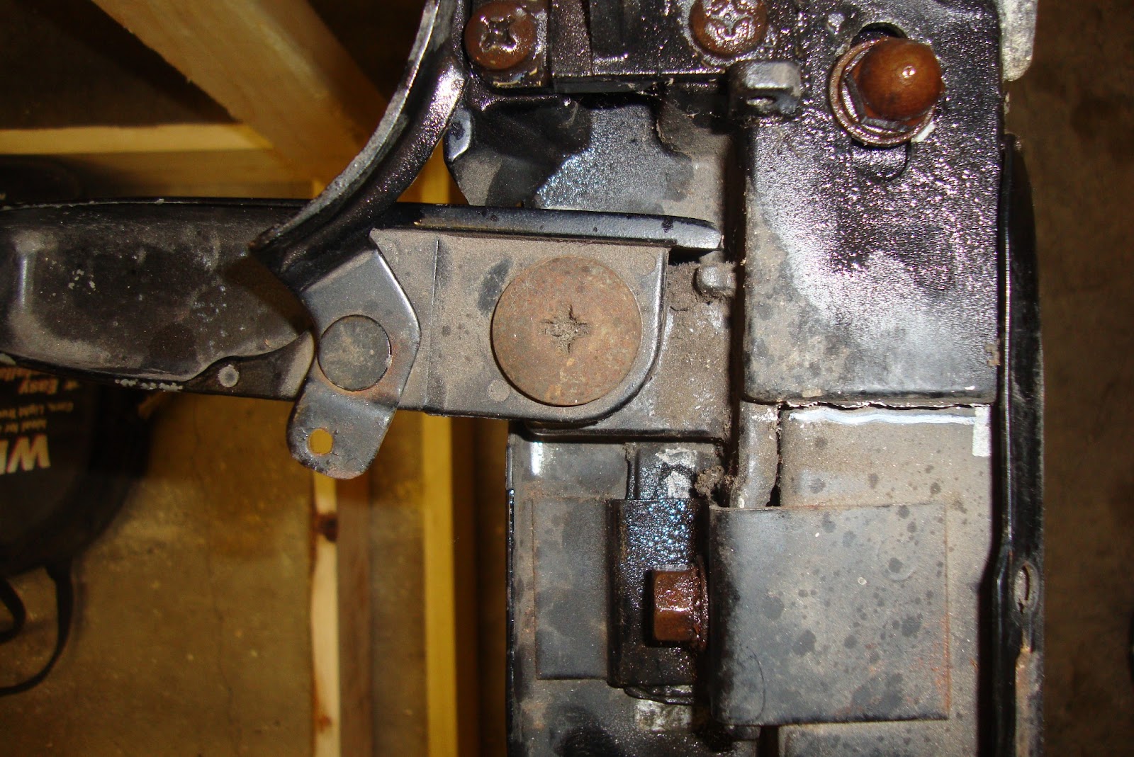
The header bow is removed from the frame by removing the acorn nut from the top and the lock nut from the inside although one side of my header bow was already loose and moving around. The header then slides out of the rest of the frame taking the latches with it as one assembly. My header bow was in pretty sad condition as the ends were badly corroded. There's a thin pad glued to the top/front edge of the bow which I then scraped off.
 |
| The acorn nut at the top and the lock nut at the bottom middle are removed to remove the header bow. |
 |
| Header-less |
 |
| The header bow ready for tear-down. |
 |
| Nasty corrosion. |
After the header bow, I removed bow #2 which simply involved removing an acorn nut off of a hinge pin followed by bow #3 which was held to the frame by a pin that came out with the removal of a cotter pin. That pretty much separated the middle segment of the frame from the rear segment. Bow #4 could then be removed from the rear segment by removing a pin held in with a cotter pin. The rear segment also houses one end of a bar called a "balance link". That bar is held to the rear segment by a pin held on by a spring cotter pin. Finally, the rear segment is held onto the base frame bracket with a big pin that's press fitted into bushings in the rear segment. Pop those pins out and the rear segments come free.
 |
| This pin holds the #2 bow on. |
 |
| This pin hold the #3 bow on and the middle segment to the rear segment. |
 |
| This is what happens when you pull just the two bow pins. |
 |
| This holds on the #4 bow. |
 |
| Almost apart. |
 |
| This holds on the balance link bar. |
 |
| Removing the main pivot pin exposed the dirty secret. The bushing was DOA which is probably why the pin kept popping out. |
 |
| The base frame brackets are all that's left. |
After the frame was broken down, it came time to strip the old paint and rust off of them, primer them, and paint them with a semi-gloss black engine enamel. I just chose the engine enamel because it's what I've grown accustomed to spraying all throughout this Ol' Rusty project. However, I've found at least one reference where people claim that the frame could be e-coated (same as powder coating?) and that the bushings could withstand the heat but don't quote me on that. Now, regarding tear-down, I didn't take this project to nearly the level it could be. Every bushing is being reproduced and a
kit is available from time to time by VMF user
Raven. These kits, at the cost of $265, although worth every penny, are beyond my budget so I have opted not to replace the two linkage bushings in the middle segment. If I were to replace these bushings, the linkage pivots would have to be pressed out and then re-peened somehow since they are not serviceable. However, should you decide to go this route, there's no reason you can't fully disassemble every moving component of the frame, remove all of the bushings, and power-coat the whole kit-n-kaboodle.
So, on with the Ol' Rusty version of "restoring the top frame". The header bow needed lots of special attention. Firstly, the corrosion on the ends had to be ground away. I wanted to grind it all the back down to bare metal so it would never take hold again and in doing so, the header bow looks a bit worse for wear but since it's mostly covered by top fabric in the end, I wasn't as concerned about it. I just needed to make sure that the corrosion stopped and never started again. I ground it with both a brass bristle brush on my bench grinder as well as steel wire brushes for my drill. Eventually, I got back down to shiny metal. That wasn't all though because the large 5/16" truss screws that act as pivots for the latch handles, were stripped out. I had considered simply filling the holes with JB weld and redrilling and tapping the threads but decided instead to go with a
Helicoil 5/16" 18 TPI thread repair kit. I drilled the hole out to the specified size, tapped it with the included tap, and threaded the insert into the hole. The hole was about twice as deep as the insert so I stacked two on top of one another and clipped the excess coil from the last insert.
 |
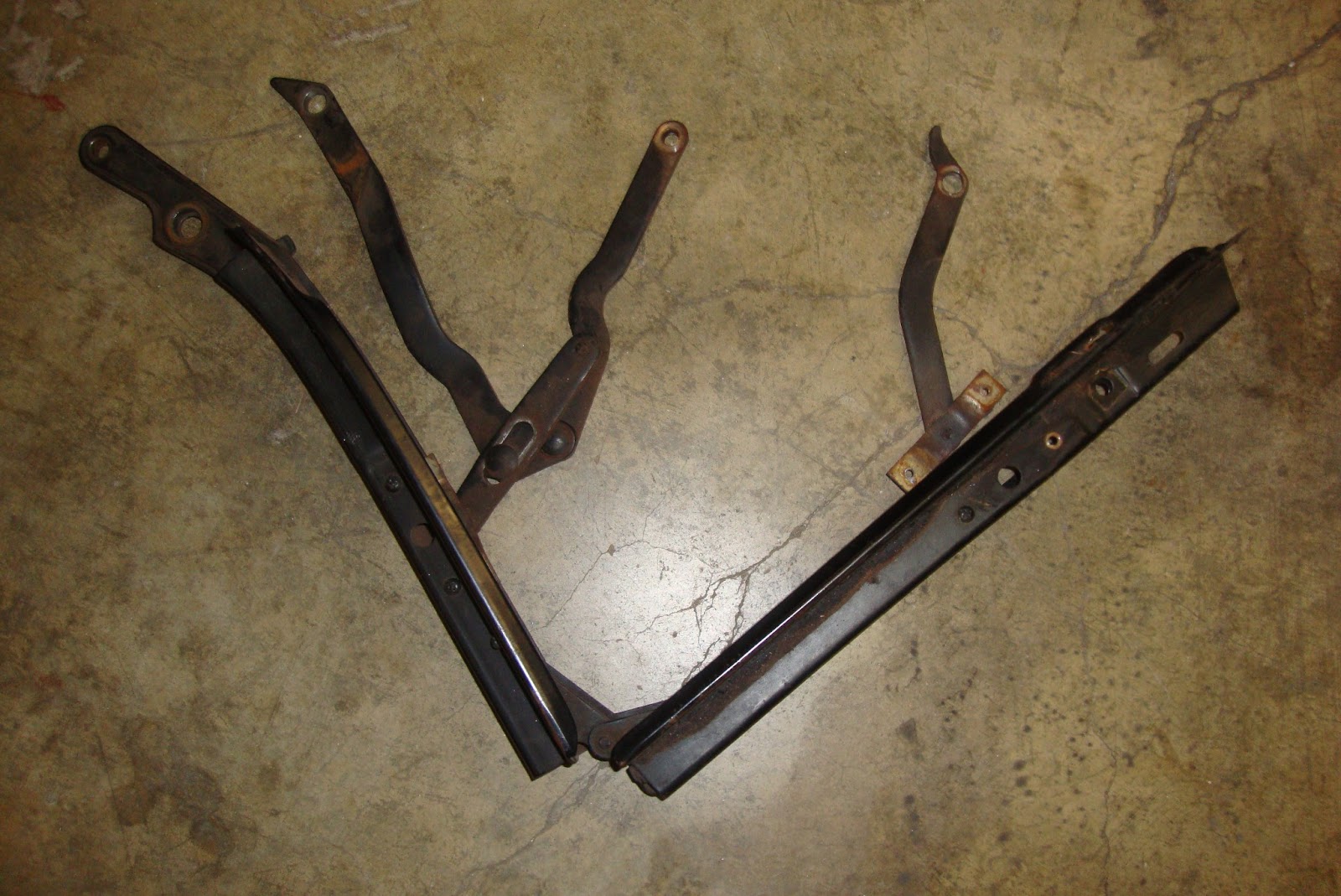
| The front and middle frame segments and linkages. Each linkage assembly is held on by two screws. |
 |
| Frame segments and linkages stripped. |
 |
| Header bow tack strip drilled out. |
 |
| Header bow after the corrosion is ground away along with most of the loose paint. |
 |
| After the latch assembly has been removed. |
 |
| Stripped out.. what to do? |
 |
| All frame members cleaned up and in etching primer. |
 |
| Helicoil hole drilled, tapped, and first coil segment inserted |
 |
| Second Helicoil segment inserted. |
 |
| All frame parts painted. |
I had disassembled the latch handle mechanisms and media blasted the parts in addition to the various pins and fasteners which were cleaned up and prepared for paint. The bushings were cleaned up with lacquer thinner and scuff pads. The fasteners and latch parts were then primed and painted with semi-gloss black engine enamel.
 |
| Latches stripped and ready for paint. |
 |
| Fasteners cleaned up and ready for paint. Bushings cleaned . |
.
 |
| Fresh paint and cotter pins. |
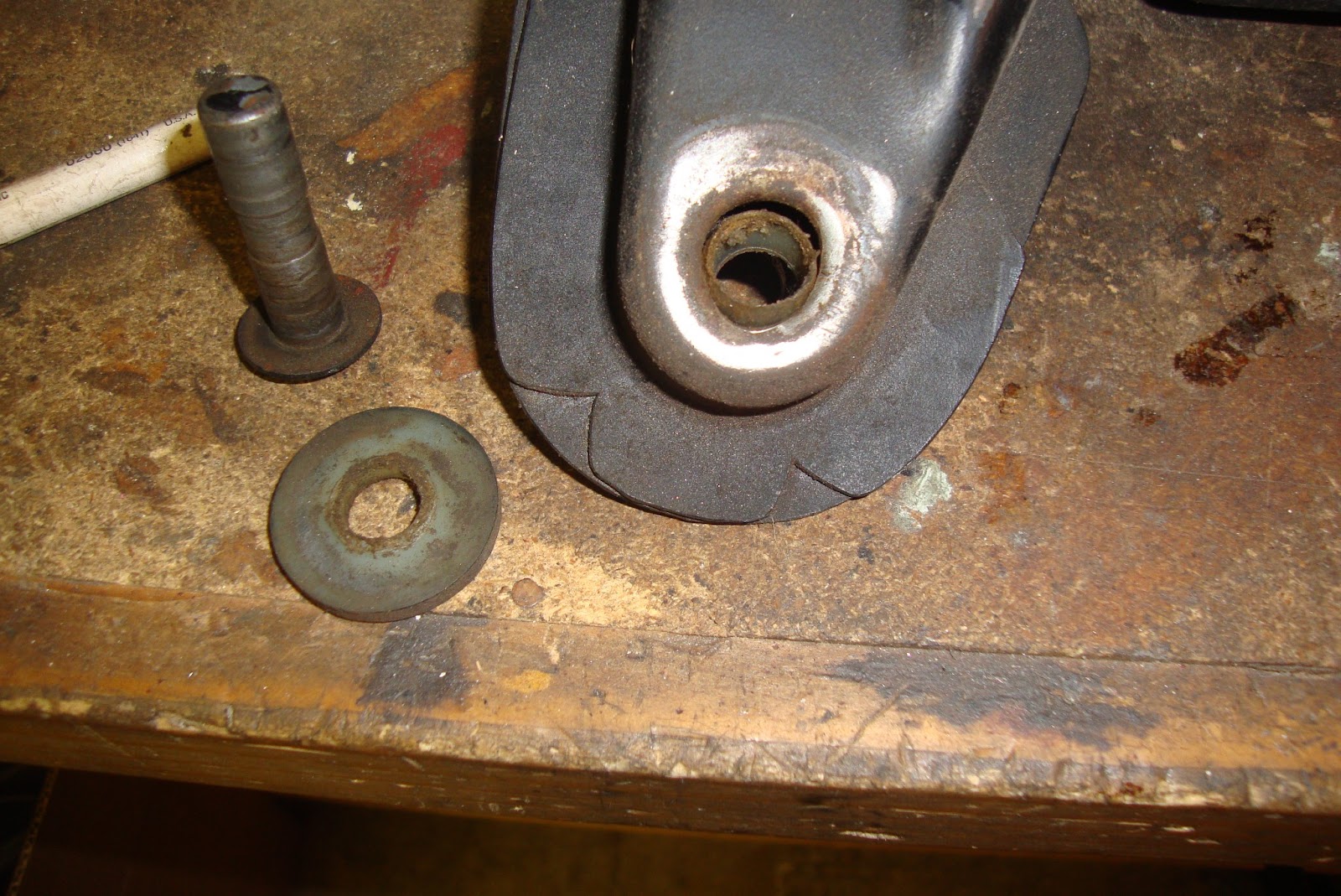
The driver side latch mechanism was a replacement with very poorly fitting fasteners being used so it was more sloppy than the original passenger side in addition to the truss screw being stripped out so additional repair was needed. Firstly, the OP had drilled out the pivot of the mounting plate which used to have a press-in pin. The pivot was tapped for a 1/4-20 screw which had no way of locking itself into the plate so it would work itself out. I made a headless stud that could be threaded all the way in and tightened against the shoulder at the end of the thread which proved more effective at locking it in than a standard screw and also isn't as likely of breaking off the pivot plate's tab or bending it in.
 |
| The new pivot stud compared to the old screw that was being used. |
 |
| New pivot stud torqued in. |
 |
| This is what the original pivot looks like on the passenger side. It's pressed in. |
There are two small bushings in each of the latch hook assemblies that support a pivot pin and spring on which the latch hook rides. Both sides had a damaged bushing so I moved both good bushings to the original passenger side handle and put that side back together. For the driver side, I found a pair of bushings with as close of an ID (inside diameter) and OD (outside diameter) as I could and drilled the plate in which they mounted to fit the new bushings and drilled the ID of the bushings to the correct size of the mounting pin. The flanges were still too large so I chucked the bushings up in my drill and ground them down with a dremel spinning a carbide side-cutting mill bit until they fit inside of the spring (see below).
The final repair to be made to the driver side latch handle was the pivot of the handle itself which was currently a 5/16" nut and bolt which I felt looked really bad so I cut off a clevis pin and ground a groove in it to fit a C-clip. The driver side handle was then reassembled.
 |
| Broken latch pivot bushings. |
 |
| New bushings with ID drilled out next to original. |
 |
| New bushings "re-machined". Pivot drilled out to fit the new bushings OD. |
 |
| Latch pivot mounted to the pivot plate with new bushings for the latch hook block. |
 |
| Latch hook block spring installed over the bushings. |
 |
| Latch hook block with pin ready to be pressed in. |
 |
| The replacement handle pin. This was an ugly and bulky nut/bolt. I cut off a clevis pin to length and ground a C-clip groove in it. |
 |
| Update 2/23/2013: The hook blocks are on the wrong sides. The "ramp" on the chrome part should be facing up in this picture. |
The header bow needed a new tack strip since I had drilled the rivets out of the old one prior to painting the bow. I bought replacement
tack strip from NPD and some 3/16" rivets from my local Ace. I drilled out and riveted the first point and then scuffed the tack strip channel of the header bow. Between each rivet, I drilled the hole for the next rivet and spread some contact cement until all rivet points were done. The ends of the tack strip where the bow curved had to be clamped until the cement cured.
 |
| New header bow tack strip and rivets. Rivet holes drilled out to fit. |
 |
| Starting to rivet the strip on. |
 |
| Clamping corners for contact cement. |
 |
| Refurbished header bow. |
The latches were then re-installed on the header bow. Three screws hold the pivot plate on and the one large truss screw acts as the pivot for the handle. Finally, the spring is attached. Both of mine were missing so I bought
new ones.
 |
| Installing the latch handle |
 |
| Handle truss screw tightened down into it's new Heli-coil threads. |
 |
| New springs. |
Another feature of the header bow was a strip of padding glued along the top-front edge of the bow. This padding felt to me like.. well, felt.
Dalorzof of the VMF mentions the use of an 1/8" x 2" self-adhesive foam tape. However, I wanted to find a form of felt to be contact-cemented like the original. I found on Amazon, a "
pipe wrap insulation" that seemed to fit the requirement that happened to be 3" wide. Also, I ordered in some
3" wide black duct tape to simulate the tape that was evidently wrapped all along the front edge of the header bow overlapping the tack strip and the padding. I cut down a strip of padding to 2" wide, masked off a portion of the header bow, and sprayed a coat of 3M contact cement on the bow and one side of the pad and stuck it on. I then wrapped a strip of tape over the front edge to overlap the padding and tack strip.
 |
| The 3" duct tape and header bow "padding". |
 |
| Comparison of original padding to new. |
 |
| Padding has been contact cemented onto the bow. |
 |
| The bow with new padding. |
 |
| And covered with tape. Kinda wrinkly :-( |
Now that the major repairs are completed, I could move on to the reassembly of the frame. The first step was to insert the new
main pivot bushings that I had bought from NPD. Immediately, I discovered that the bushings were too large for the holes. Upon closer inspection of the NPD site, I read that
"some cars may have a 9/16 inch O.D. bushing but we are not certain where and if the deviations happened". Well, that deviation landed right on my face because I'll be dipped if my frame members don't have the mysterious 9/16" holes. So, panic set in as I realized that my weekend may very well be shot as I'll have to find, order, and wait for, a set of the correctly sized bushings (the NPD outside diameter is 5/8" by the way). I considered simply drilling out the frames to 5/8" but the holes are punched, such that there's a kind of flange around the inside diameter of the holes that would be obliterated by a larger hole and I was concerned that the sharper edges of the cut holes would cut into the plastic bushings causing them to fail too soon. I posted a call for help on the VMF and generally, the best option was to cut the bushings to fit 9/16. Good luck finding a machinist on a Saturday so what to do? Well, I didn't have a proper machinists lathe but I did have a few things that I could put together to cut plastic.. hopefully accurately. Firstly, I had a large Harbor Freight drill press with a fairly adjustable round table. Secondly, I had a large Harbor Freight cross-slide vice. Lastly, I had some broken 1/8" carbide mills that I had used with my Dremel. I bolted the cross-slide to the drill press table, and trapped the bushing on a 3/8" bolt which I chucked up into the drill press. I used my angle grinder to grind a 45-ish degree bevel in one end of the small carbide mill and clamped it in the cross slide vice and adjusted everything such that when spinning up the bushing, the cross slide would bring the tool against the bushing. I found that if I orient the tool at the bottom of the bushing, the drill press could be used to move the bushing up and down against the tool while carefully adjusting the cross-slide to push the tool further into the bushing. Every fine pass, I would check the outside diameter of the bushing with my digital caliper until it was about .01" larger than 9/16". I did this for all four bushings and they all came out just right if I may say so myself.
 |
| The original bushing compared to the hole compared to the new NPD bushing. Something ain't right! |
 |
| My poor-boy "lathe". |
 |
| NPD bushing compared to the newly "machined" bushing. |
 |
| Bushings installed in the rear frame segment. |
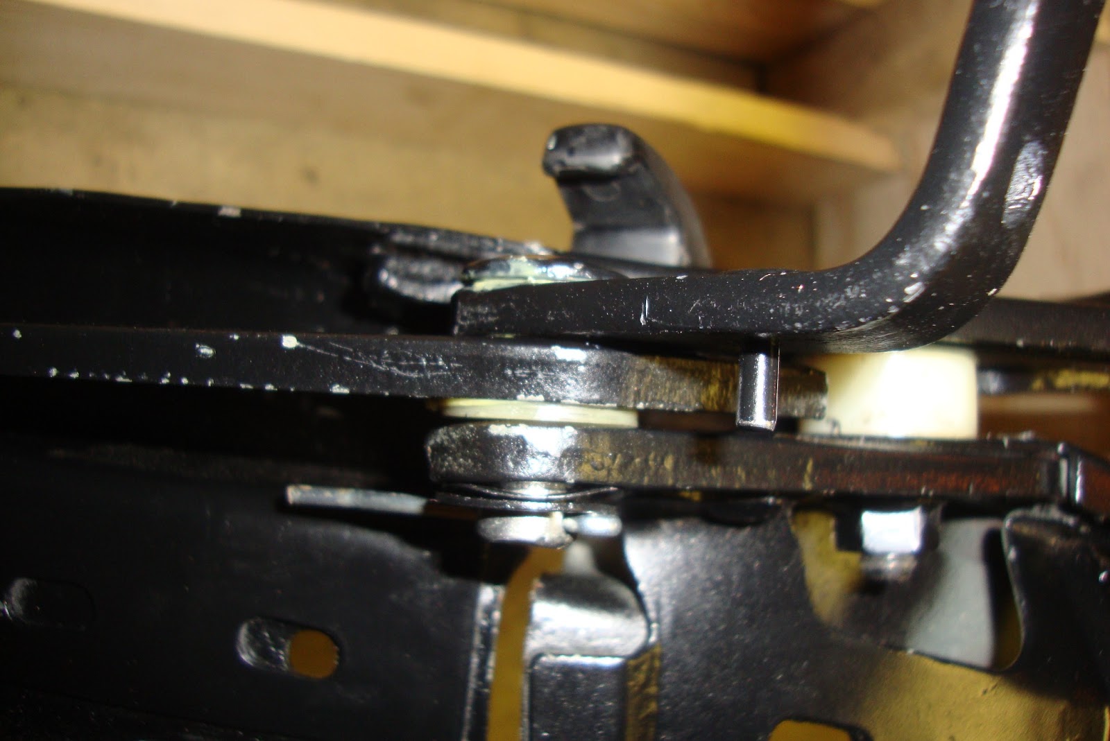
I lubed up the main pivot pins and inserted them into the rear frame segments. The balance link bars were also attached to the main bracket with its bushing and pin which was also lubricated. There's an eccentric adjuster that was lubed and installed in the other end of the balance link bar.
 |
| Rear segment on the main pivot and balance link bar. |
 |
| Balance link pivot/eccentric pin. |
 |
| installed. |
The center frame segment was then affixed to the first by inserting the bushing from the balance link bar into it's pivot hole at the end of the middle segment. The large pivot screw and it's large round bushing/separator was then lubed and threaded into the hole in the side of the rear frame segment and a nut tightened onto the exposed thread. One of the more complicated linkages on the top frame is the #3 bow pivot to front segment linkage to rear frame segment pivot. All of this is held together with one long pin. I had previously separated the bows from their L-brackets for cleaning so now I'm just installing the L-brackets and saving the bows themselves for later. The #2 bow pivot is attached to the front-to-middle segment linkage ends via another shorter pin that also has a threaded, flattened, end that is used to adjust the height of the bow #2 by loosening the acorn nut.
 |
| balance link and middle segment attached to the rear segment. |
 |
| #3 bow pivot installed. |
 |
| #2 bow pivot installed. |
The #2 and #3 bows were then attached to their L brackets via 4 screws. The #2 and #3 bows are different lengths with the #2 being the shorter of the two. My #3 bow was also bent front to back which I had to straighten before installing it.
 |
| #3 bow installed. |
The header bow was then installed on the ends of the front frame rail segments via two studs. The top being the shorter stud with the acorn nut and the longer stud having a locking nut. The final adjustment will be made after installing the frame back onto the car.
 |
| Header bow installed on the frame. |
I went ahead and adjusted the alignment of the middle and front frame segments using the eccentric adjuster on the end of the balance link bar. I just loosened the large nut and rotated the eccentric pivot with a hex key until the segments were straight across.
 |
| Frame alignment. |
 |
| Frame alignment adjuster. |
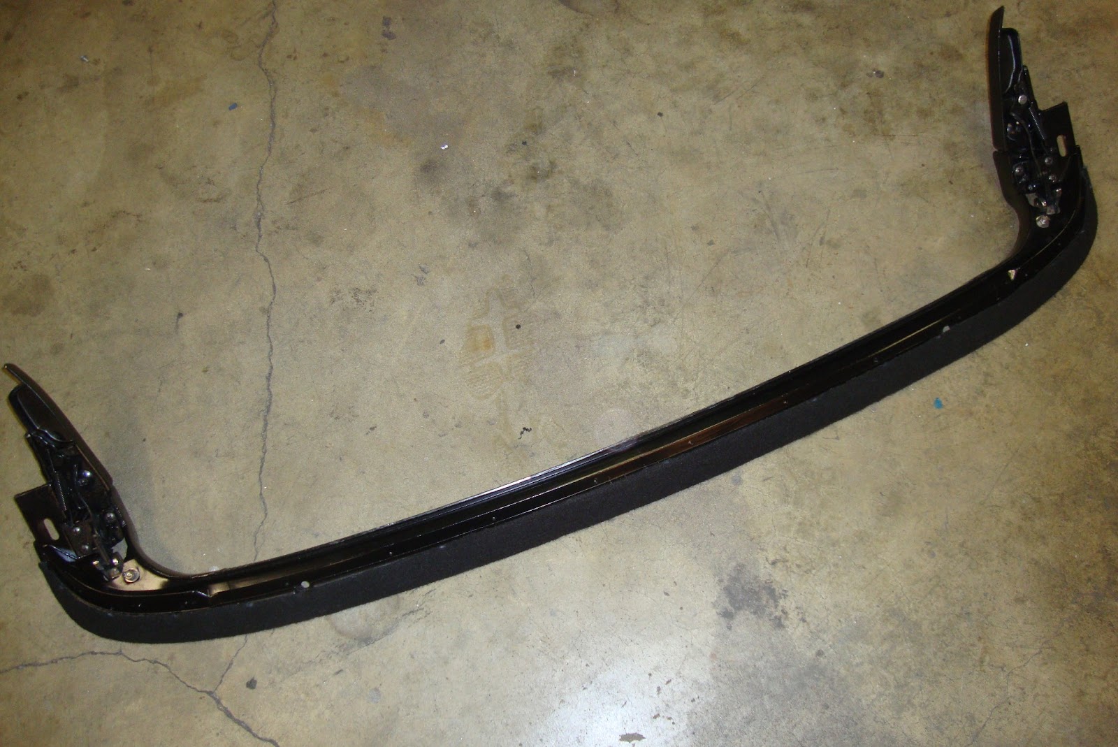
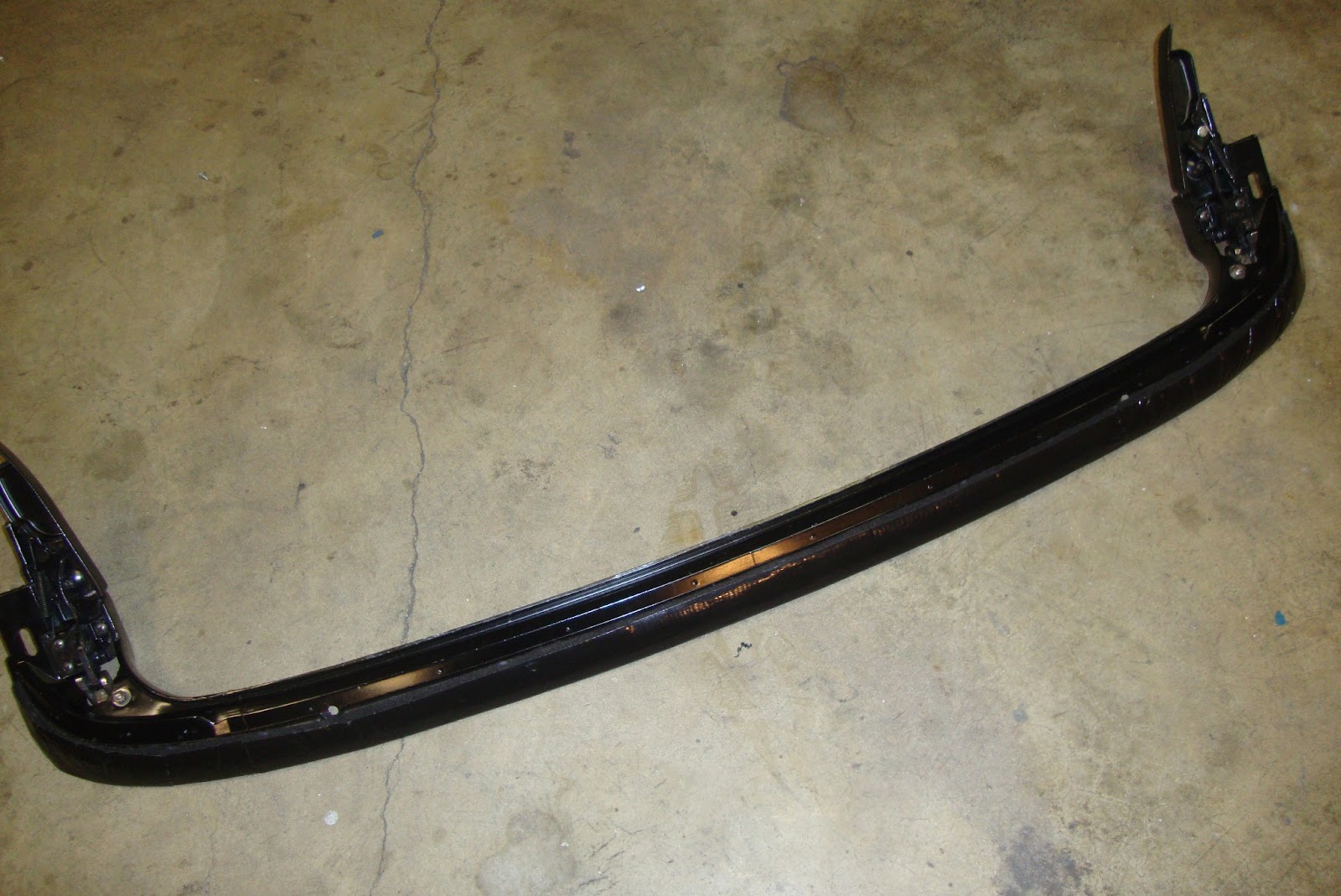
The frame restoration and assembly is now complete with the exception of the #4 bow in the rear which I will wait until the frame is back on the car since that bow is a kind of a big floppy pain in the butt and I didn't want it chipping the new paint on the frame (or the car for that matter).
 |
| Done! (rear bow excluded) |
Next I'll be installing the refurbished frame.


Wow doesn't even begin to express my amazement of your work! I'm telling you Alex, you could write a book on Mustang restorations. This 'vert top segment makes me wish I had one just so I could follow your procedure. The NPD bushing mod is excellent! You da man!
ReplyDeleteLOL! Thanks Dennis. Who needs a book when we have the interwebs? I'd have liked to do a full-blown restore, pulling apart everything, getting it powder-coated, and replacing ALL of the bushings, but maybe somebody else will have the funds to do that and blog it up in the future. For now, this is good-nuff for a driver. Thanks for the support!
Delete"The bushings could withstand the heat." -Alex O.
ReplyDeleteI said don't quote me on that! ;-)
DeleteGreat work on refurbing the top Alex. As for the heli coils, we use them exclusively at my job, and it takes a lot to make them fail. Can't wait to see it finished!
ReplyDeleteThanks Grant! Yeah, I was impressed with how easy they were to install.
DeleteMy hat is off to you for doing the refurb yourself. My frame ('67) was in better shape than yours and I still wimped out and bought a complete new one! Now I'm just storing the OEM unit while I try to find a buyer
ReplyDeleteThanks Edbert. Good luck on your project.
DeleteHey so on the corroded ends of the header bow how did you repair them? I am considering using bondo to fill in the 1/2”-1” edge missing on my passenger side. With a new header bow being $400-$550 I’m wanting to see if I can just repair the edges thanks
ReplyDeletePhill
I didn't repair them. Just ground the corrosion away with a wire wheel and painted it. The header bow padding covered it from sight.
DeleteI have a 68 frame I just started to try and get it to open up and it won't, gets stuck about halfway. I think I will remove it from the car like you did and tear it apart, rebuild it. Thanks for this information. I was getting ready to bite the bullet and pay 1300 for a new one. You have inspired me to rip it apart and rebuild it!
ReplyDeleteThanks Dan. Glad I could help.
Delete