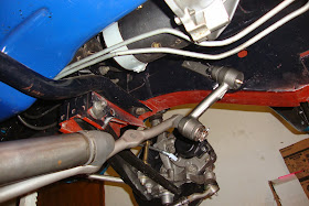
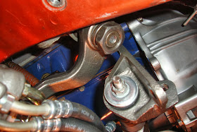
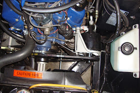
After
rebuilding the pump, I cleaned up the main and water pump pulleys (the non-A/C V8 power steering system uses a 2-groove water pump pulley and a 2-groove main pulley), the pitman arm, the center link, and the various brackets and fasteners that came in the "kit" I bought from the seller of this system.
Now the control valve could be threaded onto the center link but there's a rather involved method to doing this to ensure proper tolerances and, blah-de-blah. However,
Dan at Chockostang lent me a bit of his hard-earned wisdom which was to simply look for the divot that the center link pin made in the slot of the control arm sleeve over the 40 years of operation and align the pin hole with that. Sure enough, there was a light indention in the inside wall of the aforementioned slot which I marked with a pencil and threaded the control valve onto the center link and re-inserted the pin at the position of the pencil mark. The sleeve clamp was then bolted on.
 |
| Parts ready to go! |
 |
| Indexing the split pin at it's original location |
 |
| Clamped |
Next, the power cylinder's end stud was torqued to the value specified in the manual which meant that the cylinder-to-control valve hoses could be fitted. I had purchased a set of
concours style hoses from CJ Pony Parts only to find that they were inexplicably too short! I scratched my head for a bit thinking that the hoses were bad.. or wrong... or something and finally decided to compare the power cylinder I had used from the 71 Ranchero to the dented power cylinder I had purchased from the kit seller. Sumbish! The Ranchero cylinder was 1/2" shorter! Craaaaap. So, I went down to NAPA and ordered a pair of Ranchero-specific hoses and sure enough, they were about 1/2" longer. Go figure. I aligned them according to the many images I had of the assembly's before I had disassembled them and tried to match the twists and orientations of the hose ends and proceeded to cinch them down with wrenches and then with vice grips until they could be cinched no more (per another suggestion from
Dan in a VMF thread).
 |
| Power cylinder affixed to the center link |
 |
| Mustang power cylinder (top) compared to Ranchero cylinder (bottom). 1/2" shorter. |
 |
| Correct length control valve tubes installed |
After The cylinder-to-control-valve hoses were tightened, I connected the main pressure hose and the return hose fittings followed by a pipe clamp to hold it all together. Yes, the repro hoses had to have their bends "massaged" a bit to fall into line, so to speak. The rack assembly was ready to install!
 |
| Pressure and return lines attached to the control valve |
 |
| Ready to install the rack! |
Before installing the rack assembly, however, I installed the 2-groove pulleys, the pump bracket, and the pump. Installing the water pump pulley was probably the most difficult since the fan had to be removed and replaced and lining up the fan bolts with the pulley is always a treat. The steel pump bracket was then bolted to the front of the water pump and the long stud and spacer was inserted through the P/S pump bracket and torqued to the front of the driver-side cylinder head. The pump was then ready for business.
 |
| M/S crank pulley (left) compared to P/S pulley (right) |
 |
| M/S water pump pulley (left) compared to P/S pulley (right) |
 |
| Pulleys and steel pump bracket installed on engine. |
 |
| Power steering pump ready for business |
Now I could move on to the installation of the power steering rack. However, the cylinder arm bracket mounting holes were just left open on the driver side frame rail so I first needed to remedy that situation with the installation of a pair of
power cylinder bracket crush nuts (a.k.a. "rivnuts"). I could just insert them in the frame rail and tighten a bolt but research claims that they will crush crooked that way so a special tool should be used. The tool is pretty simple though and just consists of a bolt, nut, and washers set up in such a way that the bolt could be held straight while the nut is tightened against the crush nut. I just welded another bolt to the head of the first to use as a handle to torque against.
 |
| Crush nuts or "rivnuts" for the cylinder arm bracket to frame rail |
 |
| Home made crush nut tool |
 |
| Using the crush nut tool. Hold the handle while cranking up the nut against greased washers. |
 |
| One done. |
 |
| Both done. |
The manual rack had to be removed first including the idler, center link, and pitman arm. The tie rods were removed from the center link but not from the spindles. All joints were broken with a
pitman arm puller and the idler arm was unbolted from the passenger frame rail allowing the manual rack to be dropped away. To pull the pitman arm though, I had to buy a new 1 5/16" socket. Unfortunately, 1/2" sockets (my max wrench size) max out at 1 1/4". After that, they go to 3/4" which I don't have so I had to drop another $6 on a 1/2" to 3/4" adapter.
..
 |
| Big-azzed socket and 3/4" adapter. |
 |
| Popping off the M/S pitman arm. |
 |
| Popping the tie rods off the M/S center link. |
 |
| The M/S rack is out |
With the old manual rack out the way, I could now bolt in the new one starting with one idler arm bolt and then lifting the other end of the rack up and inserting the vertical cylinder arm bracket bolt to support the weight of the new assembly. The steering box was then centered and the pitman arm was installed generally parallel to the frame rail torquing the nut down to around 150 lbs using my newly purchased 1 5/16 socket and 3/4" adaper. The other end of the pitman arm was then mated with the input stud of the control valve, torqued, and pinned. The tie rods were then mated with their respective center link holes and the idler arm was fully bolted to the frame rail and all were torqued and pinned as required. Finally, all three mounting bolts of the cylinder arm bracket were torqued to the driver frame rail.
 |
| The steering-less car ready to accept it's new power rack |
 |
| One bolt in the idler arm first to support one side. |
 |
| Power pitman arm aligned and installed |
 |
| Power rack installed. |
 |
| Idler arm installed and aligned for center. |
 |
| Pitman arm attached to the control valve input stud and hoses run up towards the pump |
The hoses were snaked up between the driver-side exhaust manifold and the shock tower toward the pump. Almost all of the required brackets were included in the setup including half of the hose bracket that ties the power steering hoses to the shock tower (via one of the motor mount bolts). The lower section was missing so I fabricated it out of a 14 gauge scrap I had laying around. The rubber isolator was inserted into the top section of the bracket which was bolted to the lower section and then bolted to the motor mount on the shock tower.
 |
| Factory bracket top (right) and my fabricated bracket base (left). |
 |
| Hoses routed through the isolator with my bracket base bolted to the motor mount |
 |
| A shot to show the hose bends as they enter the isolator bracket. |
The end of the return line was slid onto the return port of the pump and clamped. The pressure output line was looped next to the shock tower and tightened onto the output port of the pump. The power steering belt was then installed and tightened and the pump pivot bolts were torqued.
 |
| Hoses affixed to the back of the pump. |
 |
| Fluid ("F" ATF) added and ready to fire up for the first time |
I then poured about a quart of power steering fluid into the top of the pump, gritted my teeth, and started the engine. There was an ungodly growling noise at first as the fluid was sucked out of the pump and squished into the cylinder. I ran the steering wheel back and fourth several times from lock to lock to bleed the air out of the system and then shut off the engine, topped off the pump, and did it again. The growling finally subsided and the steering began to feel... powerful. I repeated the exercise of steering from lock to lock and topping off the pump several times until the fluid level remained steady. I crawled back under the car with a flashlight to check for leaks and found none! I dropped the car off of the jack stands and soon discovered that the wheel could easily be turned from lock to lock with one finger with the car sitting in place. Gotta love it! I called the wife out and we went for our first power-assisted evening drive. During the drive, I noticed that when driving straight, the steering wheel was cocked a few degrees to one side. That boggled me a bit since I had checked, double-checked, and triple-checked the steering box center while hooking things up. The best I could do is shrug and remove the steering wheel and re-center it.
 |
| Wheel cocked off to one side when driving straight? Nothing that pulling the wheel and setting it straight couldn't remedy. |
Despite the steering wheel weirdness, It tracked okay but I took it to Les Schwab the next Saturday for an alignment anyway (with the arning drop specs in hand). The car was done within an hour and I received the alignment report indicating that the steering was within my specs. The alignment guy had mentioned that my camber was set very high which is why it tracked okay despite being out of alignment. This also, might be why I felt that my manual steering was difficult to manage (fighting me on cornering). Perhaps a lower camber with the manual rack wouldn't really be that bad? Live and learn I guess.
..
 |
| Getting Aligned |
I took my wife for another evening drive and this time, it was heavenly. I must admit that the manual steering box, although it works fine in a power-steering system, leaves a bit to be desired in the responsiveness category. Don't get me wrong though. It's still a good driver, just the extra turns on the manual steering box makes the steering "float" a little but still easy to get used to. Regardless, I got my hands on a proper power steering gear box but that will be another entry for another time.
I've actually been driving the car with power steering for several weeks now and I'm very happy with it for the way I use my car which is lots of slow cruising and maneuvering. I also feel that the control at higher speeds is better when taking fairly tight corners. Also, lane correction at highway speeds feels like way less work. All-in-all, this is one of my favorite mods and I'm happy I put in the time to do it.
UPDATE 10-31-2014: Around January of 2014, I started experiencing severe slippage of the belts. I'd install a new belt and it would work fine for a while and start slipping as well. I finally tracked it down to the wrong crank pulley. The groove for P/S was a 1/2" whereas the belt was 3/8". I started this
THREAD on the VMF but ultimately found a working pulley that one of my local friends actually had on shelf so I bought it. The pulley was a
C5OE-6312-A and worked like a charm although it has a spare outside A/C sheave that remains unused.
 |
| The working pulley C5OE-6312-A. Showing the groove alignment. Note the spare sheave. |
 |
| Engine compartment view |


Outstanding work and instruction as always Alex! I have to admit, your thoroughness in this part of your resto will make my R&P conversion look like child's play!
ReplyDeleteThanks Sven! Honestly, I didn't think it would get this involved but as usual, I bite off more than I can chew and then struggle to not take a loss. :-)
DeleteHa! That sounds like the definition of classic car restoration!
DeleteWow, I'm exhausted just reading that Alex! What a pile of work! It's amazing how many times when googling Mustang questions, that your blog shows up in the results. You've probably helped more people than you know.
ReplyDeleteA quick note on fan/pulley alignment. Somewhere along the line, a car mentor showed me a little trick here. Just finger-thread a couple studs onto the face of the water pump flange. These will act as a guide to getting the fan aligned. Then just pull them out one at a time and replace with the proper bolts.
An old trick but worth mentioning. Love the riv-nut tool - I'll have to remember that one :)
rj
Thanks RJ! That's a great tip. I think I'll use it next time as I'm sure this won't be the last time I pop off the fan.
DeleteNever ceases to amaze me how thorough and easy to understand you make these posts Alex. Enjoy the smooth effortless ride!
ReplyDeleteThanks for saying so Grant. I sometimes have trouble balancing the desire to make an informative walk-through with the desire to make a post more entertaining.
DeleteThis man redefines the term "good ol' American know-how". Thanks for taking the time and effort to share it with us.... Man your engine bay looks so clean without anA/C compressor and hoses!
ReplyDeleteThanks Ivan! It's surely becoming a bit more cluttered though. Hopefully there will be a power brake booster up there on the firewall. Fortunately, we're too far north to really have any use for A/C in a convertible. :-)
DeleteAlex, all I can say is, "When is your Mustang restoration book hitting the shelves?" Crazy detailed documentation that will come in handy when I get to that part of my restoration...whenever that happens!
ReplyDeleteHaha! It may be awhile Dennis. :-) Thanks for the kind words.
DeleteGreat job Alex. makes me reconsider power steering again. I never could get my last coupe's power steering from leaking until I pulled it off the car.....I swore I would never go back. But then again I never went to the trouble of rebuilding the entire system either.
ReplyDeleteThanks Tom. Rebuilding it would help a lot. ;-) Don't forget to replace the hose seats in the control valve and the power cylinder though.
Delete