Okay, I've put it off for long enough but couldn't justify putting it off for any longer; The assembly of the doors.
The
breaking down of the doors was a big enough hassle that I could foresee what a pain putting them back together would be and I wasn't disappointed. Before I begin, I'd like to apologize for the absolute mess the interiors of my doors are. I didn't really notice all the white residue it before I took the pictures and downloaded them to my PC but by then it was too late to do anything about it.
The first thing I did to the doors before starting assembly was to line the widest part of the panels with
RAAMaudio sound deadener. I used one sheet per door. The doors still have their factory sound deadener applied to the outer skin so this is just another layer in addition to that.
The first part to go in was the door latch. It just inserts from the inside and is secured to the back panel of the door with 3 large Philips screws. While seating it, it helps to have the door lock rod already in position and feed it up through the inside door lock hole at the top of the door. The exterior door lock was next installed which required that it be inserted into it's hole and a spring-stop inserted into a notch from the inside of the door. The door latch lock rod could then be locked into it's retainer.
I had purchased some external door handles at the latest Portland Swap Meet. As far as I know, they're not Scott Drake and are made in China. The relatively poor quality attests to this as the exterior latch button has a lot of play in it. They look great and fit the door well though, so I'm letting the questionable quality slide for now. The door handles were bolted on via a screw inserted at an angle through the back panel of the door and a stud affixes the narrow end of the handle to the door skin. The exterior latch rod was then inserted into it's rod retainer. The door latch rods are adjustable so I adjusted it to where all slack was taken out of the latch lever such that the rod's "L" end was aligned with the hole in the handle retainer and then the rod was tightened one more turn. This put just a little pressure on the latch spring and ensured that a push of the button would completely unlatch the door. This completed the install of the latch... for now. The internal door lever will be installed later in the build.
 |
| Sound deadener. Sorry about the white crud at the bottoms of the doors. |
 |
| Latch installed |
 |
| Exterior door lock clipped in with rod inserted into it's retainer. |
 |
| A close up of the internal door latch mechanism. The top-right rod is the adjustable door latch rod. The lower two rods are the internal (left) and external (right) door locks. |
 |
| New door handles. |
 |
| Door handles and lock installed. |
 |
| The two mounting points of the door handle. |
 |
| The completed door latch mechanism and where the rods go. |
Next came the window guides. The rear guide also contains an upper door stop. Loosen this but do NOT remove it. You'll have hell to pay if you wait to put it in until after the window is installed. The guide rail lube was an interesting compromise. The Ford
factory manual called for a "Polyethylene Grease". I read all of the
cans of grease at NAPA and found nothing that even remotely resembled
"Polyethylene". I finally decided that it was an obsolete form of lube,
probably made from the blubber of some extinct species of whale or
such, and settled for "Multi-Purpose Marine Grease". It seemed to have
properties that I felt were beneficial to this task in that it is water
and temperature resistant as well as being of a fairly tacky consistency
which means that it would stick where it's placed and not melt and run
down into the doors on hot days nor freeze up on cold days. I've also
learned that the generally accepted grease that people use for guide
channels is white lithium grease. One other option is
Valvoline Multi-Purpose Grease for Ford.
Whatever you choose, you don't need to fill the channel with grease.
Rather just coat the edges of the rails inside and out where the rollers
will have the most contact.
The rail was snaked into the large access hole on the inside door panel and the bracket was aligned with it's mounting holes at the top rear panel of the door while aligning the adjustable stud at the bottom of the rail with it's mounting hole. The two small mounting bolts were loosely threaded into the top of the door and the stud nut was loosely threaded onto the adjustable stud. The rail was initially adjusted toward the inside door panel. This gave room for the window guides to drop onto the rail later.
This was also a good time to install the short regulator guide rail at the middle-back of the inner door panel. The rail was lubed and it's studs aligned with it's slotted mounting holes and their nuts tightened on. I aligned it straight across with the studs centered in the mounting slots.
 |
| Lubed up rear guide rail. Leave the window stop on it! |
 |
| Rear door components installed. |
 |
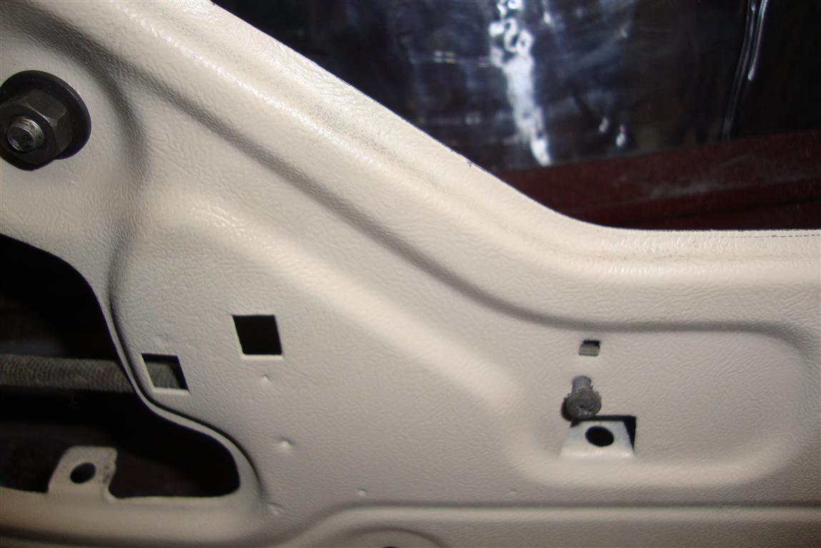
| Mounting points for the rear window guide. The center bolt is the window stop, don't forget to adjust it. |
 |
| The lower rear guide rail adjustable stud nut (left) and the rear regulator guide nuts (middle) |
The wing window was a bit more complicated as it has four mounting/adjust points. Two bolts at the top and an adjustable studs at the bottom of the window run and an adjustable stud at the bottom of the frame. The fun part here is that all adjustable studs had to be removed to get the frame to fit into the top of the door. Then the frame had to be tilted forward slightly to grant access to the holes where the studs screw in. The studs were then screwed all the way in and the window could then be fitted loosely into the top of the door. Finally, the 4 bolts were aligned with their respective mounting holes in the inner door panel and the two top bolts were loosely threaded in. The long one goes all the way through from the front door panel, through the big chrome hole in the frame, and into a captive nut in the outer door panel. The front bolt just bolts right into the top-front thread of the frame. The two adjustable studs were turned CCW (using a hex wrench) out until their flat washers butted loosely against their door panel holes and then their nuts were installed to hold them in place while I futzed with the window.
 |
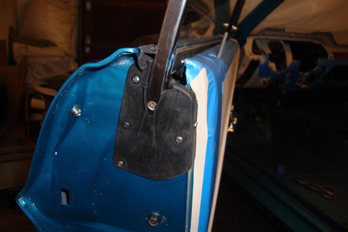
| Wing window mounting points. |
 |
| Aligning the window frame to install adjustable studs. |
 |
| Wing window assembly loosely installed. |
The window has two captive rollers at the back edge that were inserted into the rear guide rail. I cleaned these up and re-lubed them before inserting the window into the top of the door. To get the window into the door, I first tilted the front of the window into the vent window run and worked the rear rollers into the rear guide while trying to keep the front edge of the window in it's run. I held the window in the up position with a clamp while I installed the window upper stops. With the window still locked up, I assembled the window regulator by lubing up the regulator rollers and the window channel and placing the channel on it's rollers on the regulator. I snaked the whole she-bang into the door's access port and inserted it's guide roller into the short guide rail at the rear of the door installed earlier. I then worked the regulator crank shaft into it's hole between the door panel and the wing window run. Finally, the four regulator mounting bolts were inserted and tightened.
 |
| Side window with rollers lubed up. |
 |
| Side window inserted and held up with a clamp. |
 |
| Front window stop inserted. |
 |
| Rear window stop access hole. |
 |
| Window guide rail |
 |
| Guide rail mounted on the regulator. |
 |
| Inserting the regulator into the door. |
 |
| Crank has been aligned and regulator bolted in with 4 star bolts. |
 |
| A view of the short rear regulator guide rail. |
I placed the window crank on the shaft and cranked the window regulator up and positioned the window a little down until the window rail holes aligned with the window frame captive nuts and inserted each of the three window guide screws waiting to tighten them until after all three were in position. The window was then deemed "crankable".
 |
| Aligning the middle rail hole with the middle window mounting point. |
 |
| Aligning the front rail hole with the front window mounting point. |
The inside door handle shaft was then bolted into its place in the inner door panel and the long rod from the door latch was inserted into it's retainer. I discovered that the long rod can be installed wrong. You have to make sure you install it with the bends aligned so the rod is closer to the door panel. My first instinct was to install the rod away from the panel but soon discovered the little clamp that holds the rod against the door panel that's impossible to install unless the rod is correctly oriented.
 |
| Inside door handle shaft installed. |
 |
| Inside door handle shaft from the inside. |
 |
| Front door components installed. |
 |
| This is the clamp screw that holds the inner door latch rod against the door panel. |
Now the actual alignment procedure is a little fuzzy because it was about an hour or two of adjusting, testing, moving, adjusting, testing, etc. until the window seemed to roll up and down smoothly, aligned with the vent window run, and the vent window run aligned with the A pillar. Also, the top of the window had to ultimately be centered in the door when all the way down and the rear of the window has to align with the quarter window (which also needed adjusting to pull it all together). Generally, the rear window adjustments that affect alignment against the quarter window and centering of the window when down, is the rear guide rail. The adjustable stud at the bottom tilts the top of the window in and out and the two small bolts at the top of the rear window guide do a lot to center the window within the door. The vent window adjustments are similar but the two fixed bolts at the top of the vent frame really just serve to tilt the vent window fore and aft while the run and upper frame adjustable studs tilt the vent window (and thus the main window front guide run) in and out. A balance of all of these adjustments plus the rear quarter window all work together to align the windows with each other and the top seal of the car and A pillar.
Finally, the window was cranked all the way down and the door window seals were snapped in. Then the window was rolled all the way up and the bottom stop block was inserted into its slot at the bottom of the door. It helped to lube the slot up a bit first. If you install this block too soon, you won't be able to install the top window seals in the door. The height of the window at the back was adjusted to align with the top of the quarter window by adjusting the upper stop in the top of the rear guide rail bracket.
 |
| Window seals installed. |
 |
| Lower door bumper installed. |
The rear door and B pillar seals were then screwed in and the doors were done. Well, at least until I put on the convertible top and have to realign everything.
 |
| Door seal installed |
 |
| B pillar seal installed. |
 |
| Windows!!! |


