Adsense review

Monday, April 16, 2012

My 12-Step Program (for quarter window install)

I dug the quarter windows out from under my bench where they were being "stored" and found the plastic baggies full of quarter window hardware.  Now, if only I could remember how to install the darned things.  I looked through my photo archive and found that any pics I took of their removal had been lost in the "Great Accidental Photo Deletion of 2009"... A very dark day that I don't want to talk about.  I searched the web and couldn't find a suitable How To but I did find this exploded view diagram that helped a lot (also in my Ford Service Manual).

Before anything should be installed, the various bits need to be cleaned up somewhat.  I spent a lot of time with a rag and a can of lacquer thinner to remove the old grease and grime.  There was some rust on my guide assemblies so I treated them with Ospho and hit them with some self-etching primer and aluminum paint.  Not an exact match by any stretch of the imagination but good enough to spend another few decades in the recesses of the quarter panels.  One of my quarter window brackets was missing a bolt-in window stop and both had bad seals.  Luckily I was attending the Portland Swap Meet the following day where I picked up a destroyed quarter window that had both stops as well as a new set of seals allowing me to complete the job that night.  Also, I media blasted the lower brackets and gave them a new coat of black paint.

The guide rail lube was an interesting compromise though.  The Ford factory manual called for a "Polyethylene Grease".  I read all of the cans of grease at NAPA and found nothing that even remotely resembled "Polyethylene".  I finally decided that it was an obsolete form of lube, probably made from the blubber of some extinct species of whale or such, and settled for "Multi-Purpose Marine Grease".  It seemed to have properties that I felt were beneficial to this task in that it is water and temperature resistant as well as being of a fairly tacky consistency which means that it would stick where it's placed and not melt and run down into the rockers on hot days nor freeze up on cold days.  I've also learned that the generally accepted grease that people use for guide channels is white lithium grease.  One other option is Valvoline Multi-Purpose Grease for Ford.  Whatever you choose, you don't need to fill the channel with grease.  Rather just coat the edges of the rails inside and out where the rollers will have the most contact.

And now on to the step-by-step:

Cleaned up parts.

My grease of choice

I used an acid brush that I cut down to about 1/4" to spread the grease along the tops and insides of the rails and around the rollers.  Yeah, this is really "Step 1" but then that would mess up my whole "12 step program" schtick so just deal with it m'kay?

Step 1: Install the guide lower bracket with two bolts into the captive nuts in the rocker.

Step 2: Install the regulator stop (the L-shaped bracket with one bolt)

Step 3: Insert the guide assembly down into the window slot from above and loosely insert top two bolts into the captive nuts in the upper quarter panel and the single lower bolt into the captive nut in the lower guide bracket (red arrows above).  Set the guide assembly as far down and back as possible to make room for the window assembly rollers.  Note the bolt location for the regulator stop from Step 2 above.

Step 4: Align the window rollers with the guide channels from the top and lower the window assembly into the guides.  The bottom roller and stops (red arrows) should not be installed until after you drop the window into the guide channels.  Step 5: Insert the roller and bolt in the window stops.

Step 6: With the stops installed, pull the window up to the top of it's travel and clamp it in position.

Step 7: Set the regulator to the position shown above and insert it into the access hole and guide the crank shaft into it's window crank hole above.  Insert its four bolts loosely.

Step 8: Crank the window regulator down until the pivot arm is in the position shown.

Step 9: Remove the clamp from the window and carefully lower it to the bottom of its channels.  Step 10: Insert the window pivot arm pin into the lower window channel roller and snap in the locking clip.

Step 11: Grease up the Actuator Arm Guide and insert it into the access hole and insert the pivot arm roller into it's channel.

Step 12: Insert the two actuator arm guide bolts show above with red arrows.
That pretty much completes the install with the exception of the adjustment of the window to the top and the door window which I haven't installed yet.  Adjustment seems pretty straight forward as there are the three adjustment points at the top and bottom of the window guide assembly for overall window height (plus a little bit of forward and back) in addition to tilting the window in and out by adjusting the position of the two bolts in the lower window guide bracket that we installed first.  When you get it all lined up, tighten all of the bolts down, kick back, and appreciate your hard work.  By the way, new window seals can be installed with the window already in the car.  You just remove the one screw at the bottom of the rubber seal and slide them down out of the their channel in the window frame while the window is in the up position.

You can then just repeat the process for the other side.  That's great for YOU but for ME, I had another fight on my hands before I could just go dancing through the daisies and installing quarter windows for you see, my passenger side actuator guide lower mounting point had been mutilated.  Now let's not go pointing fingers as to exactly who mutilated said mounting point because that's not going to solve anything, okay?  Okay.  The bottom line is that the mounting bracket was in the wrong position because somebody welded it about 1/4" too far back.  So, I had to cut it out, repair the damage and weld it back into the correct position.

Now who went and did that?

Repaired bracket.

Welded back in with successful quarter window installation.

Quarter windows!

Monday, April 9, 2012

Rear Valance & Bumper

My rear was looking pretty good (the car! the CAR!) but to finish it out, it still needed a rear valance, bumper, and bumper guards.  The rear valance was brand  new and Steve had painted it all up nice and purty.  I installed the reverse lights in their pertinent cut-outs and started looking around for where and how to install the bumper guards and discovered that the so-called "GT valance" I had purchased didn't HAVE bumper guard holes.  Oops.. a minor oversight to say the least but this is one of those things that should have been sorted out before paint.  Oh well, I transferred the hole locations from the original valance, placed strips of masking tape over where the new holes were to be drilled and drilled them out with my step drill.  The paint didn't chip and it looks fine so I dodged that bullet.  The second issue reared it's ugly head when I went to test-fit the valance on the car.  Ahem... again, another of those things that's best done before paint that I'd failed to take into consideration... it became evident that there was too much metal on the seam that joins the trunk drop off to the rear quarter and the valance wouldn't fit snugly against the bottom of the tail panel with that flange in the way.   This one was a little more serious because the only way I could see cutting that flange was with my angle grinder and it loves throwing sparks galore and new paint hates sparks.  I laid a welding blanket across the car in the direction of the sparks and laid a couple of layers of masking tape over the exposed paint I cared about that the blanket wouldn't cover.  I then drew a cut line and went medieval on it with the grinder.  I finished up with a coating of seam sealer on the freshly exposed metal.  Everything came out okay in the end so another bullet was dodged and I continued onto the fitting of the valance.

The rear valance mounting consists of 11 self-tapping sheet metal screws along the top edge, and a captive screw on each end that inserts through the bottom rear of the rear quarter.  Not so simple is the installation of the bumper guards.  These little buggers require special brackets that are bolted to the outside of the rear cross-member with no less than three 5/16" bolts each.  One bolt goes down through the gas tank flange into a captive nut in the middle of the bracket, one bolt goes out through the rear cross-member into the upper captive nut of the bracket, and the third is driven in through the lower mounting hole of the bumper guard, through the hole I had drilled into the bottom edge of the valance, and  into a captive nut on the bottom of the bracket.  There's not much room for adjusting the position or gaps of the rear valance, if you're lucky enough to get all of the holes to line up, you're pretty much done.  The bumper guards go on after the valance via two bolts, the bottom one driven through the aforementioned lower bracket captive nut and the bottom of the valance, and the top one is driven through a hole in the rear cross-member and into the upper captive nut of the bumper guard.  Oh yeah, and lets not forget the captive screw on each end, they are helpful in holding the valance in place while you align all of the sheet-metal screws but the trick is getting them to stay on the valance.  They're supposed to lock into their keyhole slots but mine wouldn't stay so I finally became frustrated enough to glue the damned things in with some seam sealer.  After enough fiddling, I got the rear valance and bumper guards installed and moved onto the rear bumper.

Freshly painted new rear valance with lights and hardware.

Bolting reverse light in.  Captive screw is visible.

Assembled and repainted bumper guard brackets.

The mounting position of the brackets viewed from the back of the car.

The three bracket bolts.

I left too much flange when I welded in the trunk drop-offs.  Also, note the square hole in the rear quarter.  This is where the captive valance screw inserts.

After I trimmed the flange back.

Assembled bumper guards.

The rear valance mounted but before bumper guards.

Inside view of where the captive valance screws enter the rear quarter.

Installed bumper guards.


An inside shot of the bumper guard brackets.

The rear bumper was another adventure.  The chrome was just good enough that I decided to keep it for at least this first summer of driving the car but the inside was as rusty as every other part of this car that was exposed to the Eastern road salt.  Long story short, I removed the two brackets and the license plate light and used my angle grinder wire wheel to clean out the inside of the bumper.  Then I treated the rust with Ospho rust converter, cleaned it up with lacquer thinner and then wax and grease remover.  Next the inside was coated with etching primer and then three coats of DupliColor Aluminum Engine Enamel.  I media blasted the nuts, bolts, and brackets, painted them all, and put it back together.  The license plate light is of the "one wire" variety so the grounding contact points of the light bracket back to the car itself had to have the paint removed to ensure a good ground.  The light itself had to be rewired because the previous owner had "repaired" it by twisting the wires together and wrapping it with masking tape *shakes head*.  I soldered the connection, covered it with shrink tubing, and wrapped it with a strip of electrical tape for durability.  Installation of the bumper only consisted of driving four bolts through the rear cross-member, through some foam seals, and into the bumper brackets.  There's a little wiggle room for find adjustment in the bracket position as well as the bumper bolts themselves.

Don't judge a bumper by it's brackets.

It just needs a little spit-n-polish.

Cleaned up inside and painted.

Reinstalling the license plate light.

Completed bumper.

The four mounting bolts with seals

Done.. or am I?
Unfortunately, I don't usually get to go riding off into the sunset with something like this.  There had to be one more gotcha waiting for me and in this case, it was in the form of running the wiring for the reverse lights into the trunk.  The driver side had a correctly placed and sized hole for the rubber seal of the reverse light harness.  However, the passenger side had no such hole.  This is another of those things I should have noticed waaaayyyyy back before I installed the rear leaf springs.  So, I had to get creative with the drill angle and bit type but was finally able to drill the hole, pull the wiring into the trunk, and call this job done.


Such a nice hole for the reverse light wiring.

Em... something's missing boss.
There's an ongoing debate about the length and fitment of these after market valances so I've included the following pics of the ends and how they align with the rear quarters.  Personally, I'm okay with the results but for those of you that are looking for really tight tolerances, this is the net result of a stock install so you'll need to modify the valance to get better than this.  Also, FYI, the valance I had purchased is the Improved "GT" rear valance from NPD.  Also, here's a LINK to an older blog entry where I compare the old valance to the new.

Driver side

Passenger side

Wednesday, April 4, 2012

Gas Tank, Quarter Extensions, and Sequential Tail Lights

While awaiting parts for under the dash, I decided to move on to an area of the car for which I had most all of the parts I needed already, the rear.

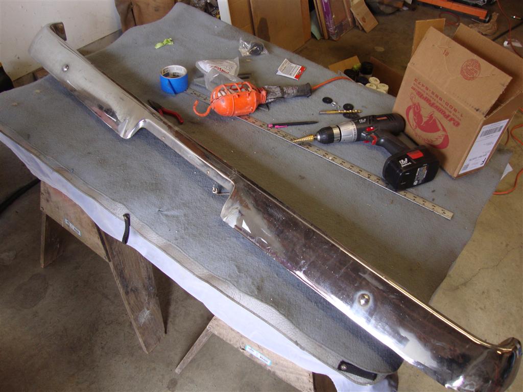
The first task at hand was the quarter extensions that were carefully packed away by Steve when he painted the rest of the car so I unpacked them one at a time and laid them carefully on a foam sheet (that was wrapped around the fuel tank for shipping) and set to preparing them to be returned to the car.

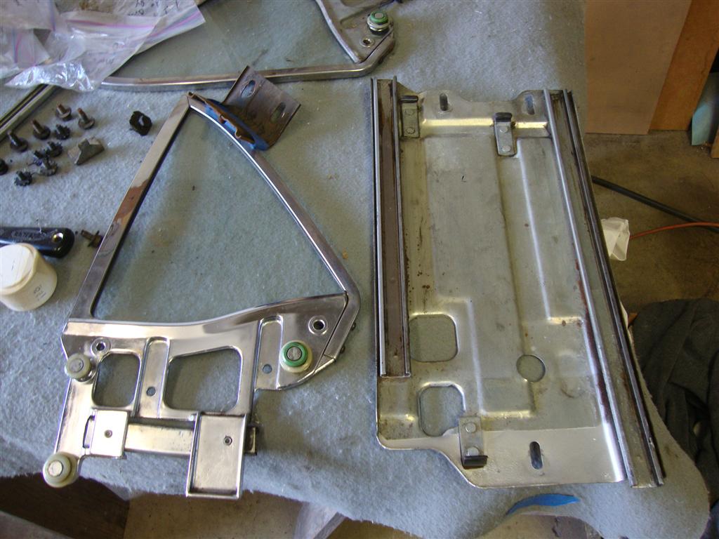
The assembly of the quarter extensions pretty much just involves installing a segment of trim, the mounting studs, and a rubber seal. Installing the studs is pretty straight forward.  There's a rounded end and a flat end.  I screwed the flat end into the extension housing and left the rounded end pointing out, presumably to help start the mounting nuts later.  I ran two of the nuts against each other on the stud and used the top nut to tighten the studs into the housing and then removed the nuts and repeated the procedure on each stud.  My trim was pretty beat up so I bought repro trim which each came with a set of mounting studs and nuts.  The repro trim is very fragile.  It's basically just thin aluminum whereas the original trim is a thicker stainless so if you can salvage your stainless, I'd recommend it instead.  Pressing the plastic stud retainers into the groove in the trim takes quite a bit of force so you have to be careful not to Lenny the heck out of the trim while you're working.  Finally, the rubber strip is fed into its groove and trimmed at the correct length.  The assembled quarter extension could then be aligned with the top and sides of the quarter panel and then a rubber washer, steel washer, and then the nut itself could be tightened onto each stud.  The whole process was repeated for the second extension and then onto the next task.

Everything we need for the driver side.

Installing the studs in the trim

Quarter extension assembled.

Driver extension mounted.

Other side.   Is that gap at the top normal?

From the inside.


The next thing I did was to rewire the tail panel for the lights.  I wanted to do this task before the gas tank so I could sit in the gas tank opening.  I ran the original harness across the back of the tail panel, up along the side of the car under the door jam and into the dash area.  The blue wire in the images below are the new 18 gauge 12 V power line run from the driver-side firewall to the passenger side of the tail panel.  You'll have to read on to figure out why I ran this line.

Passenger wiring.

Driver wiring
 
The next part I had decided to install was the fuel tank.  A new tank from CJ Pony Parts with the 20% discount and free shipping only ran about 100 bucks for a kit with a new fuel sender.  I opted not to install the original tank simply because I have no desire to clean all of the varnish, rust, and other contaminants out of it not to mention just generally cleaning up the exterior of the tank to make it look decent again.  Lastly, all the lines between the tank and the freshly rebuilt carb are new and I don't want to risk contaminating them either.

I removed the tank and hardware from it's box, removed the wrapping and immediately had to straighten the corners of the mounting flange as all 4 were bent from shipping.  Also, there was a sheen of oil coating the outside of the tank from the sheet metal press and/or general protection of the steel so I first scrubbed the tank with soap and water followed up with a rub down with wax and grease remover.  After I was sure it was clean of dirt and oil I sprayed the entire tank with a couple of coats of enamel clear coat.  After the clear cured, I installed the new fuel sender.  There's a good article on how to do this on Mustang Monthly web site that applies nicely.

New Tank

Cleaned up and clear coated.

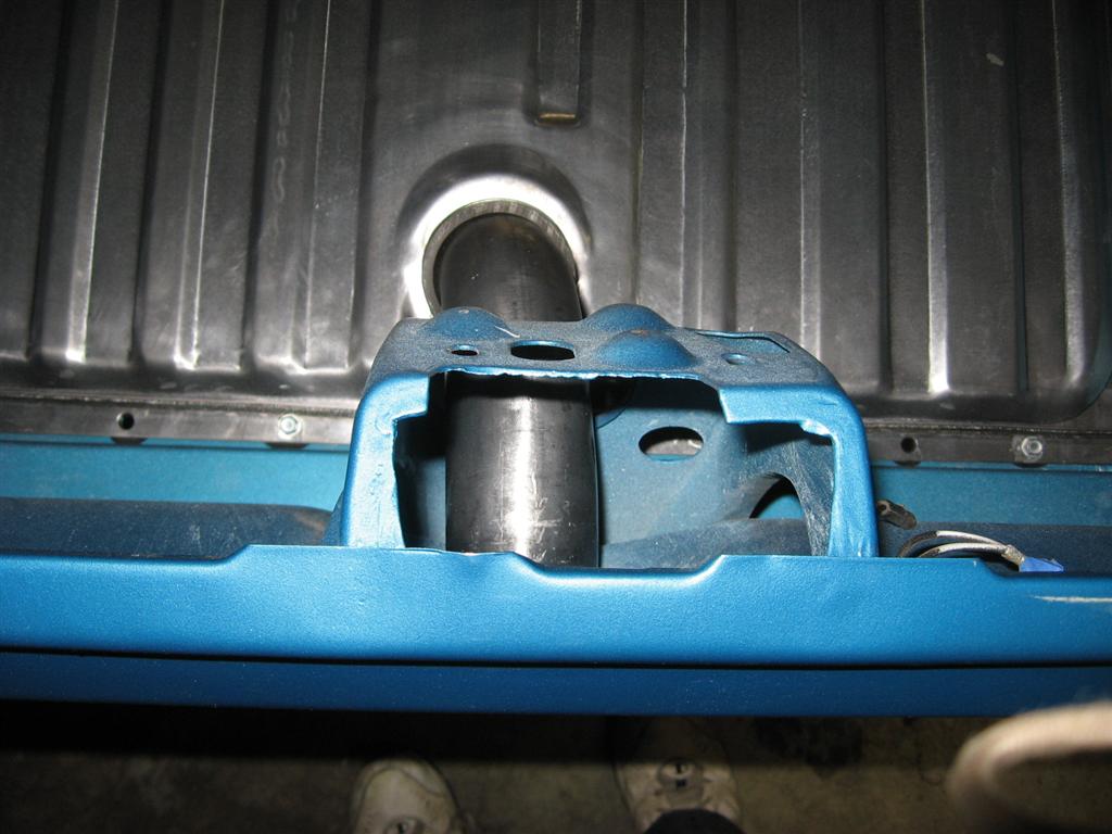
The car's tank opening also required preparation by a thorough cleaning with soap, water, and wax and grease remover.  Finally, I laid down strips of 3M strip caulk around the lip of the opening and around the various bolt holes.  The tank was then dropped in and new screws were driven in.  I was actually surprised that even after my replacing both trunk floors, all of the pre-drilled screw holes lined up perfectly with the new repro fuel tank!  Finally, I clamped a new fuel filler rubber hose onto the top of the tank and fed the filler neck through the hole in the tail panel (don't forget the gasket!) and then clamped it into the rubber filler hose.  It's about now that I discovered that I could only find 2 of the 4 required filler neck mounting screws (the 5th hole is for the fuel cap retaining ring stud) so I ordered a set from CJ Pony Parts (sale was still on) and continued onto the next task.

3M strip caulk

Strip caulk laid out on the gas tank opening

Tank is bolted in.

Filler neck installed.

Missing the screws.


 The next task was the assembly of the tail lights.  Now, normally, this is a task in itself with the two seals, the lens, the light socket, the housing, and 3 bezels per light but that just wasn't complex enough for me so I went out and bought a Scott Drake sequential tail light system.  If you're expecting the latest, greatest LED technology here, you'd better look elsewhere because this boy is on a budget and the LED system was a good 50 bucks more (when I bought it anyway, looks like it's only $30 more now).   I'm okay with this lower tech option though because LED is just a little too high tech for this car.   LED lights are very noticeable in that their brightness and color are off from all the other lights on the car and they tend to be instant on and off which I generally like... for newer cars.  But for this old girl I like the thought of the bulbs lighting and cooling as they sequence giving the sequence a kind of analog "flow" rather than a digital 1 / 0 look

A little side story: My tail light housings were both rusted out with the lower rear lips eaten by cancer so I was bummed when I found that that new repro housings cost about $40 each.  I checked eBay and couldn't find any good used ones for a reasonable price and just by chance I checked Craigslist and a guy in a neighboring town a couple miles away had a set (a pair!) for $15.  I immediately called him and arranged a meeting.  I met him the next day and was floored by the great condition they were in and noted the Fomoco stamp.  I gave him $20 and scampered happily back to my shop with my new housings.  What a deal!

The lights came in a very "do it yourself" box of parts.  I guess I'm just happy I didn't have to solder the control boxes together for this particular project.  Each reflector assembly was partitioned into three sections each containing an 1157 bulb. The wiring harness for each side had to be constructed per the instructions.  The kit came with crimp-on connectors but I always have to over-complicate things so I opted to solder all of the connections with the exception of the control box connectors and the interface between the new harness and the original Mustang tail light harness.  Three of the common wires from the reflector insert went to the original tail light wire while the remaining three wires went into the control box via the supplied control harness.  Three remaining wires from the control harness went to power (a special 12V line had to be run from the firewall back to the tail lights), ground, and the turn signal line.  The reflector assembly was placed into the original tail light housing and the wires were fed through a provided grommet.

Now, these kits aren't without a certain element of danger.  The seal that goes between the lens and taillight housing needs to be thicker than the stock seal to place distance between the 1157 bulbs and the lens to prevent the lens from melting if you're sitting on the brake too long!  Of course, my kit didn't come with these special thicker seals so I had to improvise.  Fortunately, I had accidentally bought two sets of lens seals so I just doubled them up in the housing.  Then the lens was screwed into position, followed by the big thick rubber seal that's laid down on top of the lens.  This process was repeated for the other side with some slight improvements in the construction of the harness for the other side that were learned during the construction of the first one.  Oh, and now the tail lights have a Right and Left designation.  The wiring harnesses are color coded differently for each side as well so I drew a small "R" on the bottom of the right housing and a "L" on the bottom of the left housing so  I didn't accidentally mix them up.

The kit

One side with wiring harness assembled.

Close up of the assembled harness

Reflector mounted in the housing

Doubled-up lens gasket.

Lens installed.

Rubber seal installed.

Both lights (front)

Both lights (back)


 Finally, the tail lights were mounted back onto the tail panel with brand new Scott Drake bezels which come with new studs but unfortunately not new nuts so I had to blast and paint the originals for reuse.  I haven't mounted the tail light control boxes yet.  I'm going to keep them safely in their box until the wiring for the car is complete and the tail lights are ready to be lit so they don't get damaged.

I then cleaned up my deck lid latch and MUSTANG letters and mounted them into place.  I snapped the picture below and then my camera died.   Not shown is the rear trim that I have also installed across the back of the deck lid.


I've got a new camera on order for my wife so I'll be taking her old one to use in the shop for blogging.